Why a capacitor string needs a data bus at all
A battery management system exists mostly to prevent damage: keep the cells inside a chemistry-specific envelope or they degrade, vent or worse. A supercapacitor module's electronics have a different job. The cells cannot run away thermally and do not need charge tapering, but a sixteen- or forty-eight-cell series string has one structural weakness that only data can manage — the string is only as strong as its most-divergent cell, and divergence is invisible from the terminals.
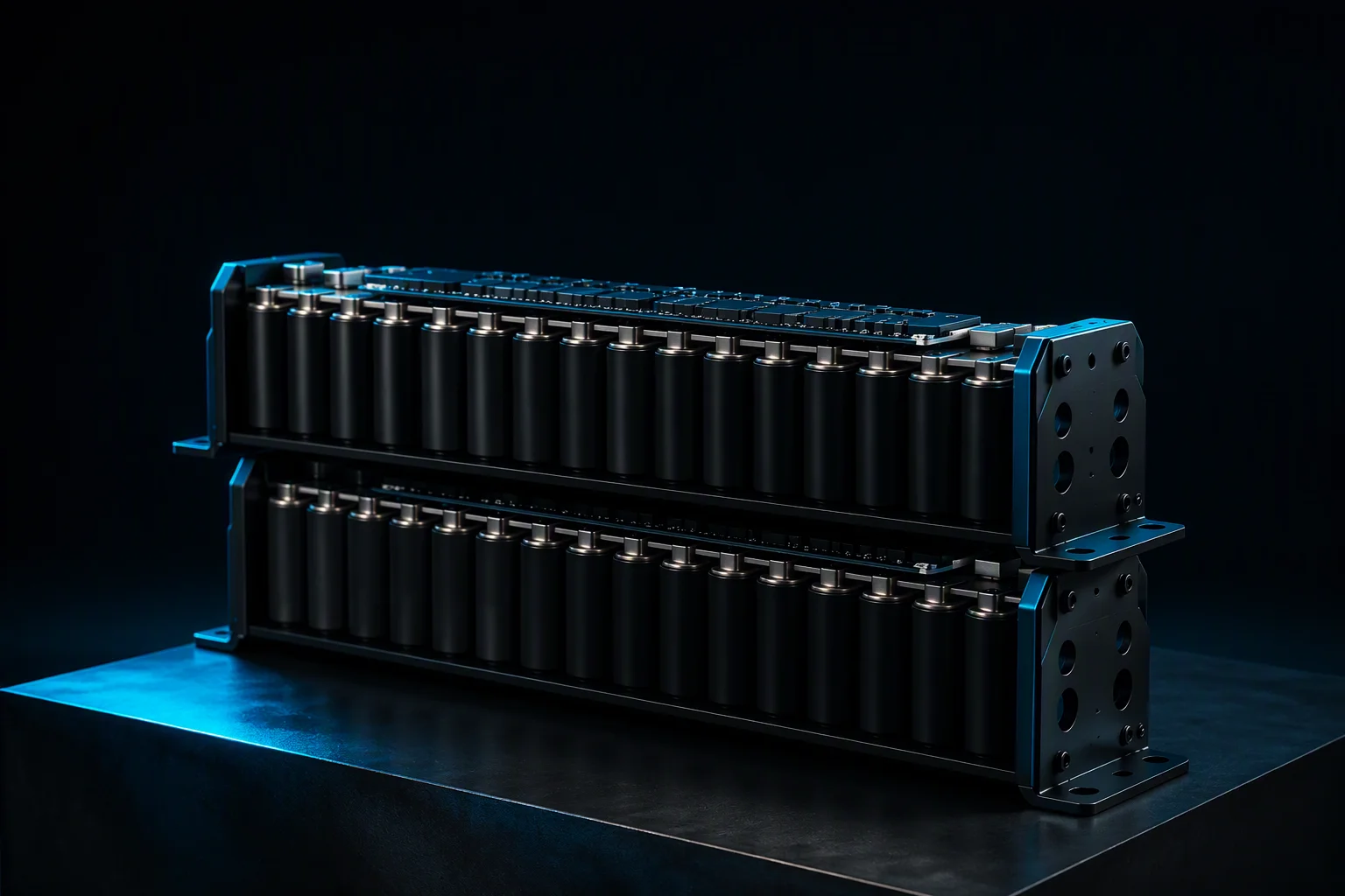
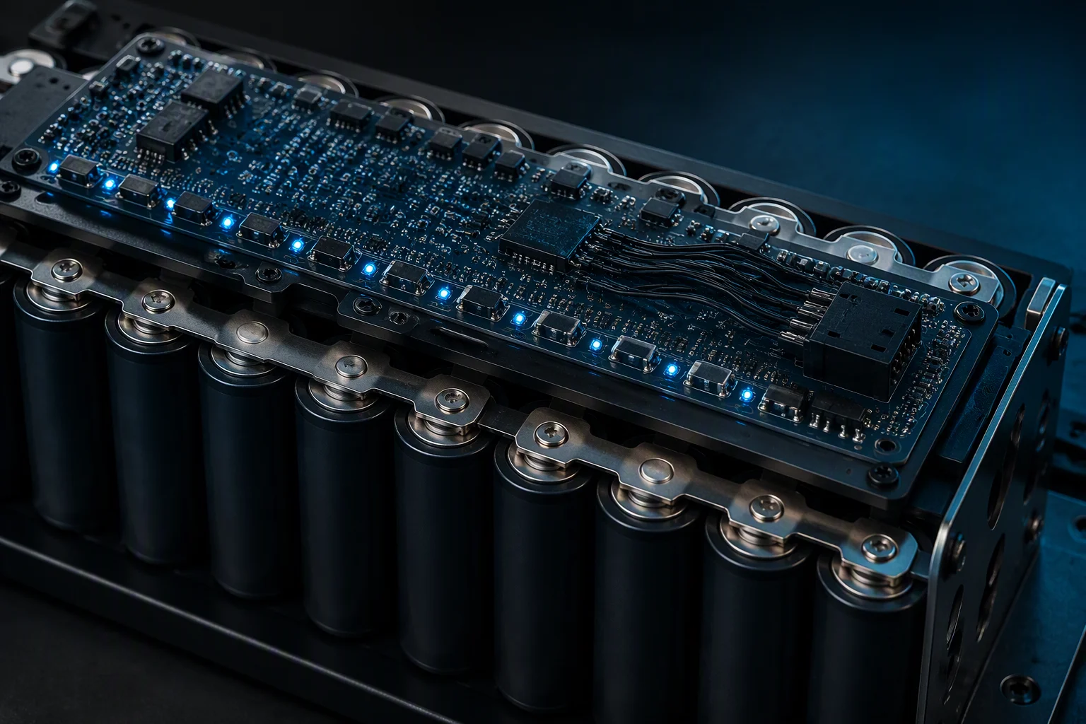
Two things happen inside a string that nobody sees without per-cell sensing. Voltage divides unevenly across cells whose capacitance and ESR have drifted apart, and heat concentrates in whichever cell has the highest ESR. Both are slow, both are measurable, and both are cheap to correct if the controller knows about them early. That is what the management board on a module is for: per-cell voltage, module temperature, balancing status and an alarm ladder, published on CAN 2.0B so the rack controller can act.
The physical layer and the frame budget
Classic CAN 2.0B — 11-bit identifiers, eight data bytes per frame — is the default for module telemetry because it is robust in a rack full of switching power supplies and because every rack controller already speaks it. Before choosing it, though, it is worth doing the arithmetic on how much of the bus one module needs. It is a lot less than most integrators assume.
- A 16-bit voltage per cell packs four cells into one 8-byte frame: 16S needs 4 frames per report cycle, 48S needs 12.
- Add a summary frame, a status frame and an alarm frame at the fast rate, plus temperature, balancing and identity once a second: about 63 frames per second for a 16S module and 143 for a 48S module.
- A fully loaded classic CAN frame with bit stuffing is around 135 bits, so a 48S module at a 100 ms report rate occupies roughly 19 kbit/s.
- On a 500 kbit/s module bus that is under 4% of available bandwidth for a full 48S module — which is why a single CAN segment can host a parallel fleet of modules without contending.
The budget is comfortable, but it is worth confirming rather than assuming, because the fleet is what actually loads the bus. Ten 48S modules all reporting at 100 ms is roughly 40% utilisation before the controller's own traffic, and that is the point at which designers start staggering report rates or moving to a dedicated module segment.
A workable frame map for a 16S module
The table below is the shape of the map we build to: what each frame carries, how the payload is packed and how often it goes out. Identifiers and scaling are frozen in the DBC file issued with the order, so your controller code is written against a document rather than against a guess.
| Frame | Payload | Rate |
|---|---|---|
| Module summary | String voltage (16-bit, 0.1 V), string current (16-bit signed, 0.1 A), min and max cell voltage (16-bit, 1 mV) | 100 ms |
| Cell voltages 1–4 | Four cells per frame, 16-bit each at 1 mV resolution — four frames cover a 16S string | 100 ms |
| Temperatures | Up to four NTC channels, 16-bit at 0.1 °C, plus a sensor-fault bit per channel | 1 s |
| Balancing status | 16-bit per-cell bitmap, balance-active flag, per-cell balance-on time counter | 1 s |
| Status and alarms | Three-level over-charge, over-discharge and over-temperature flags, hard error output state, event counters | 100 ms |
| Identity and heartbeat | Node identifier, heartbeat counter, map revision | 1 s |
Two design choices in that map matter more than the rest. Voltages report at 100 ms because a transient tier has to be observable during the event, not after it. Temperatures report at 1 s because cell thermal mass makes faster reporting meaningless — you would be publishing measurement noise. Splitting the rates keeps the bus free for the signals that actually change quickly.
Voltage reporting: resolution is the point
A 16-bit field scaled at 1 mV per count covers a 4.0 V cell with a resolution fine enough to see divergence developing. That matters, because the failure mode is a drift of tens of millivolts, not a step change. A 12-bit field over the same range gives roughly 1 mV per count as well but leaves no headroom above the ceiling; anything coarser starts hiding the signal you bought the electronics to see.
Resolution only helps if the controller looks at the right number. Publishing min and max cell voltage in the summary frame — not just the average — is what makes a problem visible. The binning arithmetic shows why: sixteen cells at the same average voltage can still contain one cell sitting 200 mV above its neighbours, and an average-only report hides exactly that. A controller watching min and max sees it in the first cycle.
Temperature reporting: put the sensor where the heat is
Temperature is the slowest-moving health signal on the module and the one most often misreported, because a single sensor placed on the enclosure wall measures the enclosure. The useful locations are the interior of the cell stack, the area around the highest-ESR cells, and the busbar joints, since a weld with elevated contact resistance is a heat source before it is an electrical fault.
Practical reporting rules follow from that. Give each NTC channel its own fault bit, so a disconnected sensor is distinguishable from a cold module — otherwise an open circuit reads as the coldest possible value and masks a real over-temperature. Report temperature alongside voltage in the same cycle, so an unexplained sag can be attributed to cold ESR rather than to a failing cell. And set the alarm thresholds against the module's published envelope: our rack modules run −40 … +65 °C, so the over-temperature tiers should fire well before the limit, while the cold end needs no heater management at all — which is one of the reasons the chemistry was chosen.
Balancing status: the frame integrators forget to ask for
Balancing is a control action that changes the measurement, and that interaction is why the balancing frame belongs in the map. When a passive bleed resistor is on, the cell it is attached to reads tens of millivolts lower than its true open-circuit state. A controller that evaluates cell divergence without knowing which cells are being balanced will chase its own corrections in a loop — bleeding a cell, seeing it look low, and stopping.
Beyond the live flag, the per-cell balance-on time counter is the most useful diagnostic field in the entire map. A cell that needs balancing for an increasing share of every hour is drifting relative to its string-mates, and that trend is visible months before it becomes an operational problem. It also gives maintenance a defensible trigger: not "the module is five years old", but "cell seven has been balancing twice as long as any other cell for the last ninety days".
Modules ship with resistive, passive or active balancing as ordered, and the board auto-balances module-to-module in parallel fleets. In standby the whole assembly has to sit below 20 µA, so balancing is scheduled rather than continuous — which the frame map has to reflect, or the controller will see gaps in the bitmap and read them as faults. The module engineering page covers how the balancing and alarm blocks are built.
Integration with the rack controller
Telemetry is only worth publishing if something acts on it. Four integration decisions do most of the work.
- Alarm ladder mapping. Level one is information for the DCIM trend log. Level two asks the controller to stop adding load and prepare to hand over to the battery BBU. Level three asserts the hard error output — a discrete signal, not a CAN message, because a protection function must not depend on a bus that a fault could take down with it.
- Node identity. In a parallel fleet, node identifiers must be assigned per module position and recorded on the as-built drawing. Two modules answering to the same identifier produce a controller that is confidently wrong.
- Physical layer discipline. 120 Ω termination at both ends of the segment, a bit rate agreed once and documented, and a stub length short enough that reflections do not corrupt frames in a hall full of switching supplies.
- Commissioning baseline. Snapshot every cell voltage and every temperature channel at commissioning, and file it next to the per-module test report that shipped in the carton. That report is the beginning-of-life measurement taken in the lab; the commissioning snapshot is the same string in its real thermal environment. Together they make later drift a comparison instead of an argument.
Finish the job with an alarm injection test: force an over-voltage, an over-temperature and a balancing fault with the controller in the loop, and confirm that the ladder behaves as documented. It takes an afternoon at commissioning and it is the only way to know that a silent misconfiguration is not sitting in your backup tier.
What to put in the RFQ
Six lines are enough to get a telemetry specification back rather than a datasheet paragraph.
- Bus bit rate, segment topology and the connector you want on the module.
- Node identifier scheme for the fleet, including how many modules share a segment.
- Required signals and report rates — which values the controller needs at 100 ms and which can arrive once a second.
- Whether balancing status and per-cell balance-on time are required, and whether active balancing is in scope.
- What the controller does on each alarm level, and whether it consumes the hard error output.
- Baseline and commissioning records you want delivered with the shipment.
Send those and the reply comes back inside 48 hours with a frame list, a scaling table and the DBC to write code against — on a standard 48 V rack module or a 16–108 V custom build with the same electronics.
Related
Keep reading
TECHNOLOGY
Module engineering: welding, balancing, BMS
How the balancing and alarm blocks are built, and the 20 µA dormancy rule.
QUALITY
Capacitance and ESR binning explained
Why per-cell voltage spreads, and what the ±5% window buys you.
TEMPERATURE
Cold start at −40 °C
Reading a cold sag correctly, and specifying for unheated halls.

Write code against a document
Ask for the frame list and the DBC.
Send the bus rate, the node scheme and the signals your controller needs — the map and scaling table come back within 48 hours.