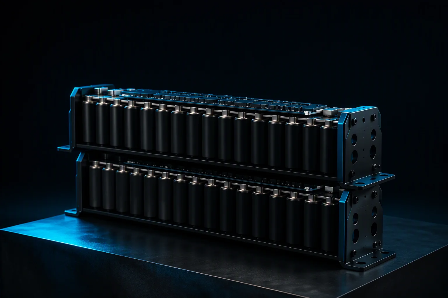
The one part of the module the builder fully controls
A module manufacturer buys cells, buys management electronics, buys enclosure hardware, and then makes one thing entirely on its own: the electrical joints between the cells. That is where the process capability of the whole line ends up, and it is also where three different problems meet — resistance, heat and mechanical strength. A cell's internal construction is somebody else's engineering. The joint is ours, and it is the part that decides whether a module still performs in its eighth year.
The duty is not gentle. A 48 V rack module moves 130 A continuously and takes surges above 500 A for events under 5 s. Every one of those amps passes through seventeen joints in a sixteen-cell string — fifteen inter-cell links and two terminals — so joint resistance is not a detail bolted onto the design; it is a material fraction of the module's total resistance.
Why welded busbars replaced cable and lugs
The conventional alternative is a cable and lug assembly: a bolted interface at every cell terminal, with a torque specification, a locking feature and a re-torque interval. That interface brings three problems at once. It adds contact resistance at a mechanical boundary that does not improve with age. It loosens under vibration, which is exactly the environment a rack, a nacelle or a tram presents. And it adds an inspection item to the maintenance plan for the life of the installation.
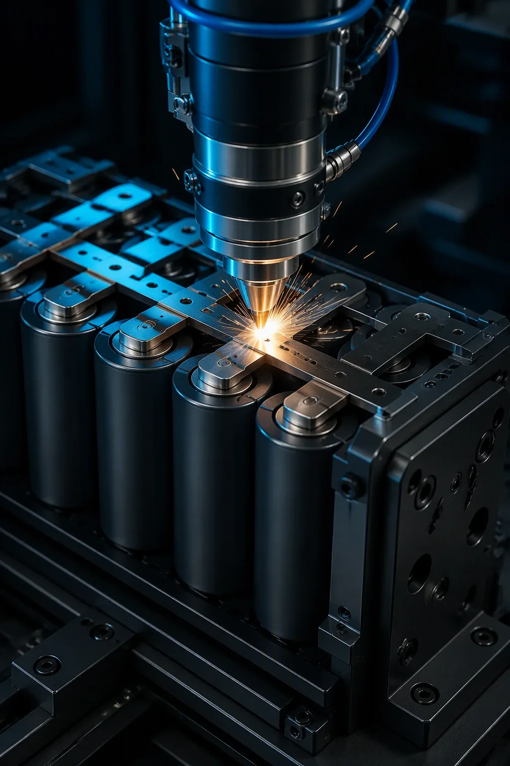
Laser welding a nickel busbar directly across the terminals removes the boundary, the fastener and the maintenance item. Weldable-terminal cells run on one fixture class and welded-post large-format cells on another, and what a laser buys is repeatability: the same energy, the same focus position and the same travel on every part, thousands of times a shift. Consistent geometry is what keeps the milliohm budget honest, and the milliohm budget is what keeps 500 A surges from turning into local hot spots.
Weld quality metrics that predict module life
Weld quality is not a single number, and it is not the appearance of the seam. It is a small set of measurable geometry and process values, each connected to a failure mode you would otherwise discover in the field.
| Metric | What it controls | Failure it prevents |
|---|---|---|
| Penetration depth into the terminal | Effective current-carrying cross-section at the joint | Cold lap — a joint that measures well when new and rises in resistance as it cycles |
| Nugget cross-section and weld width | Joining area relative to the busbar width | Local current crowding and hot spots under surge |
| Seam continuity and overlap between spots | Uniform path along the busbar, no un-melted gaps | Unbalanced current sharing between adjacent cells |
| Spatter and surface condition | Cleanliness of the assembly after welding | Contamination, fixture fouling and clearance or creepage issues |
| Positional accuracy of the busbar | Terminal stress and mounting alignment | Units that pass electrical test and fail vibration |
| Energy and power stability per weld | Process repeatability part to part | Slow drift from lens, window or focus change going unnoticed |
| Joint resistance, measured four-terminal | The electrical property that matters | Everything above, caught on the finished module |
Contact resistance: the arithmetic behind the hot spot
Heat at a joint is I²R, and because the current is squared, a resistance error multiplies straight into a temperature error. The comparison below uses the module's own ratings — 130 A continuous and a surge class above 500 A for under 5 s — against a good joint and two progressively worse ones.
| Joint resistance | Heat at 130 A continuous | Heat at 500 A surge | Energy in a 5 s surge |
|---|---|---|---|
| 0.05 mΩ — a sound weld | ≈ 0.8 W | ≈ 12.5 W | ≈ 63 J |
| 0.5 mΩ — a marginal weld | ≈ 8.5 W | ≈ 125 W | ≈ 625 J |
| 2 mΩ — a defective weld | ≈ 34 W | ≈ 500 W | ≈ 2 500 J |
Two conclusions follow. First, joint resistance has to be judged against the cells it connects: a 16S string of large-format LIC cells carries roughly 7.5 mΩ of cell ESR at 0.47 mΩ per cell, so seventeen joints at 0.5 mΩ each would add about 8.5 mΩ — more than the cells themselves. A weld programme that treats joint resistance as negligible is quietly doubling the module's resistance and halving its surge margin. Second, the failure mode is thermal before it is electrical: 500 W concentrated in a few square millimetres will cook the surrounding polymer and stress the terminal long before the joint opens. That is why the acceptance criterion belongs in microhms, not in "looks good".
Pull testing, and why it stays destructive
Tensile pull and peel tests destroy the sample, so they cannot be a production screen — and they should not be. Their job is to prove the process, not the part. A pull test programme is built like this:
- Process validation: at setup, weld coupons are pulled to failure and the failure mode is recorded, not just the force. A joint that fails in the busbar is a different result from one that pulls out of the terminal.
- First article: every new build — a new cell format, a new busbar geometry, a custom series count — starts with a destroyed sample set and a documented result before production begins.
- Periodic sampling: per shift or per lot, sample welds are pulled and retained with their records, so process drift is caught while it is still a trend.
- Acceptance criteria: derived from the terminal cross-section and the vibration profile the module will see, then fixed in the process document rather than adjusted to whatever the last sample measured.
Production units are covered by non-destructive checks instead: four-terminal joint resistance measured on the finished module, in-line vision inspection of every weld, and the surge, vibration and terminal-strength gates on the finished unit. Between the destructive samples and the non-destructive screen, no shipped module relies on a weld that was never evaluated.
How to audit an automated welding line
Automation makes weld quality consistent and invisible in equal measure: the machine does the same thing every cycle, and nobody watches it happen. The audit is therefore about records. Ask for these nine and a line becomes readable.
| Evidence | What it proves |
|---|---|
| Per-weld parameter log linked to the module serial | Every joint in your unit was made inside the validated window |
| Parameter change control records | No silent process change between your first article and your tenth shipment |
| Laser power and focus calibration records | The numbers in the log mean what they claim |
| Lens, window and optics maintenance schedule | Slow energy drift is managed rather than discovered |
| Fixture and tooling repeatability checks | Positional accuracy holds across a shift, not just on the first part |
| In-line vision results with retained images | Seam and spatter were inspected on every unit, not sampled |
| Per-shift destructive pull results with retained samples | The process is still capable today, not only at validation |
| Four-terminal joint resistance data on finished modules | The electrical outcome is verified on the part being shipped |
| Containment procedure for a failed weld | A defect quarantines the lot, not just the unit that failed |
Two of those deserve emphasis. The serial-linked weld log is what makes a field question answerable years later: given a module serial, the line can produce the welding history, the cell list, and the final test numbers for that specific unit, which is the same traceability chain behind the per-module test report in every box. And the containment procedure is the difference between a supplier that finds a bad weld and one that finds a bad weld and knows how many other units were made with the same setup.
What goes wrong, and how it shows up
Most weld defects announce themselves in a predictable order. Insufficient penetration or a cold lap shows up first as elevated joint resistance, then as heat under load, then as drift across thermal cycles, and only eventually as an open circuit — usually during the surge the module existed to absorb. Excessive penetration or burn-through damages the terminal itself, and where the weld reaches the cell's own seal area the part has to be rejected rather than reworked. Spatter contaminates the assembly and fouls fixtures, which then produces misalignment on later parts. Incoming terminal condition matters too: contaminated or oxidized terminal surfaces weld porous regardless of how good the machine is, which is why incoming inspection of cell lots is the first station on the line rather than the third.
None of this is exotic technology. It is a validated process, a calibration habit, a sample-based destructive test and a serial-linked record — the same discipline described on the factory page and in the twelve checks on the quality page. When a supplier can produce all four for your specific unit, the weld stops being an act of faith and becomes a documented part of the design.
Related
Keep reading
MANUFACTURING
Inside a supercapacitor module line
Six stations, from incoming cells to 100% final test and the report in the box.
QUALITY
Capacitance and ESR binning explained
What happens before a cell ever reaches the welding fixture.
QUALITY
Twelve checks and the compliance wall
Vibration, terminal strength, hipot and the documents behind each claim.

Audit the line, not the brochure
Ask for the weld log behind a serial number.
Send a module serial from your last shipment, or request the audit pack with your first article — the records come back within 48 hours.